Explaining the life cycle and status signals of MotoLogix functions.
MotoLogix functions can be differentiated in a few categories:
- System commands
Have a short life cycle and are processed immediately (parallel). - Motion commands
Have a long life cycle and are processed sequentially (buffered). - Common commands
Have a short life cycle and are processed sequentially (buffered).
Later in this section we will explain the behaviour of each category but first we will look at basics around using MotoLogix functions.
Prerequisites
In general MotoLogix commands require:
- The pendant keyswitch to be in remote
- Robot standstill if they are writing to persistent storage (files which can be viewed on the pendant).
Volatile data
Most data sent by MotoLogix commands is stored in the robot controller’s volatile memory. This is important to know as it means that data sent by the commands:
- Is lost after a reboot of the robot controller.
- Is not visible on the programming pendant.
INFORM jobs
Even if MotoLogix in theory can be used parallel to INFORM jobs, it is advised to prevent such “hybrid” solutions and stick with a single technology.
Status signals
Some of the status signals have a kind of special behaviour which is important to understand before starting the programming.
Except for
Sts_EN, most status signals retain their status until the next time the function is enabled.This is by design (and useful for troubleshooting) but can lead to a timing problem in the application code as the function call is often processed below the state machine logic.
As a result, the transition of the state machine can occur too soon as the transition condition (e.g.
Sts_DN) is not yet reset and still has the status from the previous run.
A code example might help to understand this phenomenon:
Example:
CASE state OF
...
10:
  // enabling the FB
  FB_Reset.Enable := TRUE;

  // condition to proceed after FB finished
  // --> Sts_DN still has its old status from previous run
  IF (FB_Reset.Sts_DN AND FB_Reset.Sts_EN) THEN
    state := 20;
  END_IF;

20:
  ...
END_CASE;

// FB call
FB_Reset(...);
// --> now Sts_DN has the new status
Sts_EN as condition.
This signal becomes active after the function call was processed and thus
helps filtering out any old status information.Keep enabled
It is not allowed to reset the Enable input of a function
before the lifecycle has completed.
This is important as one of the last tasks of the function will be to cleanup and prepare the interface for the next command.
Enable input too early can mess up the MotoLogix command
interface and lead to a hangup situation.Another important reason to keep the function enabled “all the way” is to get updates on the status signals. Especially for motion commands it is crucial to know the state of each buffered- or executing command.
Enable
input active until the motion is completed (Sts_PC).Commands
System commands
These instructions interact with the MotoLogix system state
(see MLX.SystemState).
An example of a state change initiated by a system command is enabling the
servo drives using MLxEnable.
Since system commands often need to be executed as soon as possible they do not
use the command buffer mechanism but instead each system command has its own
command bit in MLX.InternalData.WritePacket.signals.
System commands have a short life cycle and very few status bits:
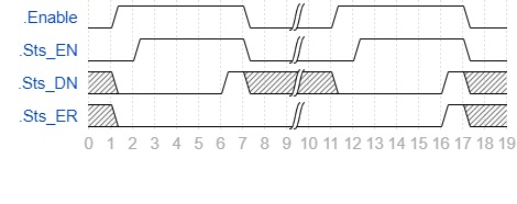
| event | description |
|---|---|
t1 - t7 | Command executed successfully |
t11 - t17 | Command executed with error |
Motion commands
These instructions send motion commands to the robot controller’s motion queue.
This uses the command buffer mechanism in
MLX.InternalData.WritePacket.Commands
where up to 20 commands can be processed (sequentially) by the MotoLogix
interface.
An example of a motion command is a Point to Point (PtP) motion using
MLxRobotMoveAxisAbsolute.
Below timing diagram not only shows the larger amount of status signals but also the longer lifecycle. This due the fact that it depends on:
- Duration of this motion.
- Waiting to finish previous motions (in case of pre-sending motions – which is the usual case).
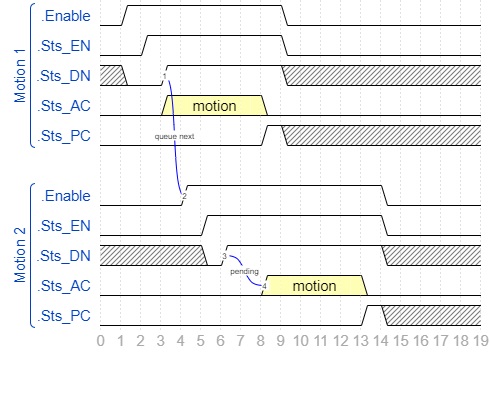
| event | description |
|---|---|
t1 - t9 | Life cycle of 1st motion command |
t4 - t14 | Life cycle of 2nd motion command |
t3 | 1st motion command added to the motion queue |
t4 | Pre-load 2nd motion command |
t6 | 2nd motion command added to the motion queue |
t6 - t8 | 2nd motion waiting |
t8 | 1st motion finished, 2nd motion starts |
t13 | 2nd motion finished |
Common commands
This last category contains all other commands sent to the robot controller.
Some instructions (e.g. MLxRobotSetUserFrame
are scheduled in the motion queue (just as the motion commands).
Others have no relation with the motion queue.
These commands use the command buffer mechanism and will be processed (sequentially) by the MotoLogix interface as described earlier.
The timing diagram and status signals are similar to the system commands:
| event | description |
|---|---|
t1 - t7 | Command executed successfully |
t11 - t17 | Command executed with error |
Transitions
Looking at the status signals and timing diagrams we can say the following for motion commands:
Sts_PC and Sts_EN is useful as a transition condition
in the application code – meaning that the motion is finished.Sts_DN and Sts_EN is useful as condition to pre-send
the next motion.And for all other commands:
Sts_DN and Sts_EN is useful as a transition condition
in the application code – meaning that the instruction is finished.Timing
When enabling multiple MotoLogix command instances each of them will get a place allocated in the MotoLogix command buffer.
But if the application code is written in such way that the robot gets only a single move command at a time – which means that the robot motions cannot be blended – the same place in the command buffer will be reused.
In that case it is important that there is at least one plc scan between disabling the first and enabling the next. This is needed to cleanup the data and prepare the interface for the next command.
CASE statement for programming your state
machines and placing the FB calls below the state machine.
This allows only one transition per PLC scan and prevents such timing issues.example of non blending motion:
// cyclically reset the enable signals
MLxFB1.Enable := FALSE;
MLxFB2.Enable := FALSE;
...
// state machine logic
CASE state OF
...
10:
  // enabling the FB
  MLxFB1.Enable := TRUE;
  // condition to proceed after motion finished
  IF (MLxFB1.Sts_PC AND MLxFB1.Sts_EN) THEN
    state := 20;
  END_IF;
20:
  MLxFB2.Enable := TRUE;
  IF (MLxFB2.Sts_PC AND MLxFB2.Sts_EN) THEN
    state := 30;
  END_IF;
  ...
END_CASE;

// FB calls
MLxFB1(...);
MLxFB2(...);