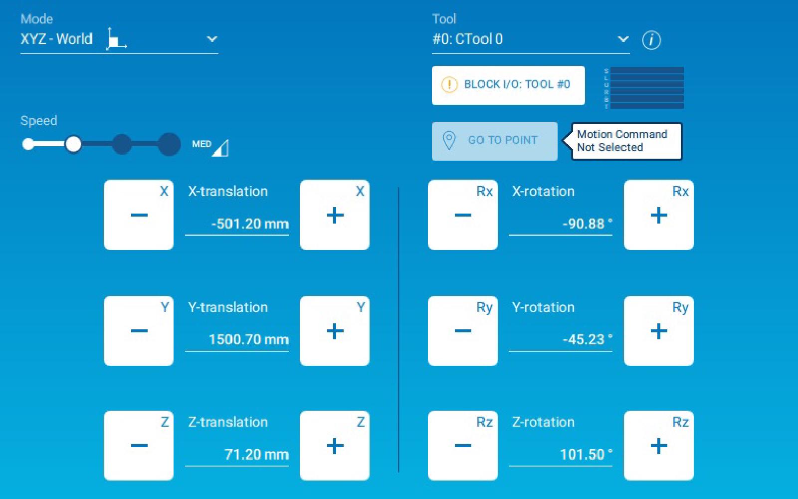
Jog commands are especially used for teaching positions. It is also useful to extract the robot from an engaged position to a known position.
Jog commands in MotoLogix allows a user to create its own interface to move a robot manually. Like the Teach Pendant, the user interface may offer several buttons, one for each available direction. As long as the user presses one button, the robot moves to the corresponding direction. Note that it is up to the integrator to design this interface.
Unlike Jog using the Teach Pendant, Jog commands in MotoLogix can only be performed while the pendant key is in REMOTE position.
In consequence, safety fence must remain closed during the operation.
Safety settings involving FSU are needed to perform Jog command in MotoLogix while safety fence is opened.
Library components
| Function blocks | |
|---|---|
MLxRobotJogAxes | Manually jog the robot axes. |
MLxRobotJogAxesToPoint | Manually jog the robot to a target axis position. This uses PtP interpolation. |
MLxRobotJogTCP | Manually jog the robot TCP (cartesian). |
MLxRobotJogTCPToPoint | Manually jog the robot to a target TCP (cartesian) position. This uses linear interpolation. |
Availability
Available on all robot and controller.
Parameters
N/A
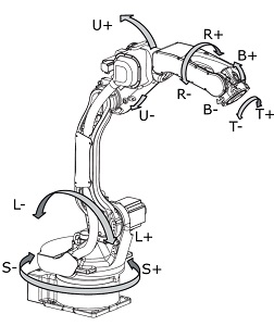
Axis JOG motion using MLxRobotJogAxes
This JOG command allows the user to move each axis of the robot individually.
The function block gets an array of 8 DINT as an input. Each variable
correspond to an axis [S,L,U,R,B,T,E,8]. Thus, robots up to 8 axis can be jogged.
The value of the variable states to which direction the axis goes. Note that several axis can be jogged at the same time.
| Value | Command |
|---|---|
| -1 | Negative (-) direction |
| 0 | No operation |
| 1 | Positive (+) direction |
Negative and positive directions for a 6 axis robot are displayed below.
Note that E and 8 axis are not used on a 6 axis robot. They are simply ignored.
Linear JOG motion using MLxRobotJogTCP
This JOG command allows the user to move the TCP (Tool Center Point) along (or around) a direction.
The function block gets an array of 8 DINT as an input.
Each variable correspond to a direction [X,Y,R,Rx,Ry,Rz,Re,R8].
X/Y/Zare translation. It moves the TCP along the corresponding axis.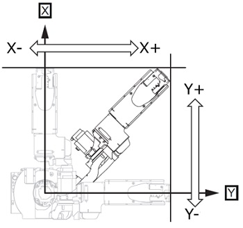
Robot translation directions X and Y 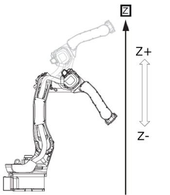
Robot rotation directions Z Rx/Ry/Rzare rotation. It rotates the TCP around the corresponding axis.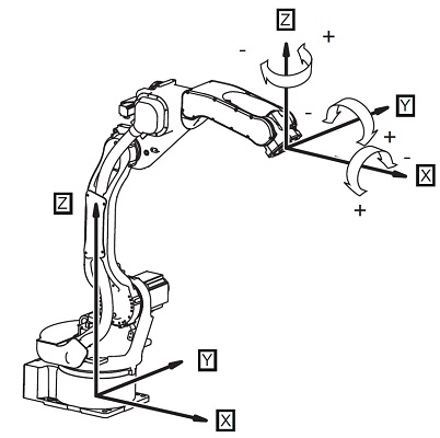
Robot rotation directions Re/R8are respectively seventh and eight axis position. In case of a 6 axis robot they are ignored.
MLxRobotJogTCP asks for a CoordFrame value. It allows the user to select the
frame in which JOG motion will be performed among the following:
CoorFrame value | Selected Frame |
|---|---|
| 0 | World Frame |
| 1 | Tool Frame |
| 2 | Actual User Frame |
World Frame correspond to the base of the robot. It is located along the first axis, on the level of the second axis. Resulting directions are given below

World Frame Tool Frame correspond to the frame located at the TCP. It is useful for approach and withdrawal of the working position. Resulting directions are given below
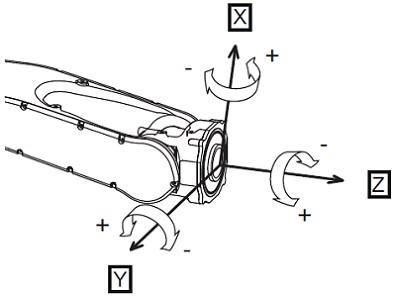
Tool Frame User Frame can be created specifically for the application. It is a frame usually used to represent a workstation (e.g. conveyor, pallet). It is useful when using tilted planes. Several User Frames can be created but only one can be active at a time (see
MLxRobotSetUserFramefunction block). Resulting directions are given below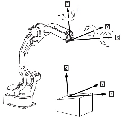
User Frame
Axis JOG motion to a point using MLxRobotJogAxesToPoint
This JOG command is used to move the robot to an Axis Position [S,L,U,R,B,T]
in axis-interpolated motion.
Unlike standard motion like MLxRobotMoveAxisAbsolute, this function block
allows the user to stop the motion when the JOG button is released.
Linear JOG motion to a point using MLxRobotJogTCPToPoint
MLxRobotJogTCPToPoint is similar to MLxRobotJogAxesToPoint. The difference
is that it moves the robot a a Cartesian Position [X,Y,Z,Rx,Ry,Rz] in a
linear-interpolated motion.
Example
First of all, to perform a JOG motion, MLX.JoggingMode must be set to True.
JOG motion starts when user presses a button and should stop as soon as the user releases it. It means that the JOG command must react fast to a signal toggle.
MotoLogix JOG command only move the robot for a small shift. The higher the JOG motion speed, the farther it goes. To achieve a continuous motion, MotoLogix JOG command must be continually called as long as the JOG signal is ON.
The state machine of the example program 2_Motion is a good way to handle this
situation. Below is a snippet from this example program.
CASE state OF

  // Other states leading to state 10

  //************************* state 10 - ready for jog *************************
  10:
    IF JogPressed THEN
      state := 11;
    END_IF;
  //************************* state 11 - jog TCP *************************
  11:
    FB_RobotJogTCP.Enable                                          := TRUE;
    IF FB_RobotJogTCP.Sts_EN AND (FB_RobotJogTCP.Sts_DN OR FB_RobotJogTCP.Sts_ER) THEN
        state := 10;
    END_IF;

  // Other states

END_CASE;
- When the system is Idle, the machine state is 10
- If a Jog button is pressed, the machine state jumps to the corresponding state (say 11)
- JOG command is issued
- When JOG command receives the Done status (
Sts_DN), the machine state goes back to 10
Keeping the button pressed will make the state machine jump back and forth between state 10 and 11. That way, and if the system cycle time is not too big (≥ 10 ms), the JOG motion will be smooth.
As soon as the button is released, the state machine will stay in state 10, waiting for a button to be pressed.
