A collection of functions for performing advanced mathematic operations.
The matrix functions enable you to do more advanced calculations in the three dimensional space. Take a look at the examples to see it in action.
Library components
| Data types | |
|---|---|
MLxMatrix | Data type for a 4x4 transformation matrix. |
| Functions | |
|---|---|
MLxCalcChildUserFrame | Calculate the user frame data (in WORLD) for a child user frame which is defined on a parent user frame. |
MLxUserFrameToCoordFrame | Convert the three taught points (ORG/XX/XY) of a user frame to a CoordFrame (X/Y/Z/Rx/Ry/Rz). |
MLxxATAN2 | Perform a standard two argument arctangent method (ATAN2). The result is in radians. |
MLxxCartesianToMatrix | Convert a cartesian position into a 4x4 transformation matrix. |
MLxxMatrixInverse | Calculate the inverse of a 4x4 transformation matrix. |
MLxxMatrixMultiply | Multiply two 4x4 transformation matrices. |
MLxxMatrixToCartesian | Convert a 4x4 transformation matrix into a cartesian position. |
MLxxUserFrameToMatrix | Convert a user frame to a 4x4 transformation matrix. |
Examples
1) Actual position in user frame [n]
Some use cases are visualization/HMI, monitoring and calculations.
This calculation is done purely on PLC-side.
It uses the actual TCP position in WORLD and the user frame data stored
in the aUserFrames array. This has a few advantages:
- actual position reading independent of the active user frame
- faster position updates (actual TCP position reading no longer needs to alternate between WORLD and the active user frame)
Functions used for this calculation:
MLxxUserFrameToMatrix– Convert a user frame to a 4x4 transformation matrix.MLxxCartesianToMatrix– Convert a cartesian position into a 4x4 transformation matrix.MLxxMatrixToCartesian– Convert a 4x4 transformation matrix into a cartesian position.MLxxMatrixMultiply– Multiply two 4x4 transformation matrices.MLxxMatrixInverse– Calculate the inverse of a 4x4 transformation matrix.
User frames
The following six user frames are defined:
![User frame [1] UF[1]](/lib-2.1.0/features/math/UF[1].jpg)
![User frame [2] UF[2]](/lib-2.1.0/features/math/UF[2].jpg)
![User frame [3] UF[3]](/lib-2.1.0/features/math/UF[3].jpg)
![User frame [4] UF[4]](/lib-2.1.0/features/math/UF[4].jpg)
![User frame [5] UF[5]](/lib-2.1.0/features/math/UF[5].jpg)
Work flow
By setting the user frame selection n (range: 0-5) the actual TCP world
position gets transformed into the selected user frame:
stateDiagram-v2

state "Collection of user frames" as U1
U1 : get data of the selected user frame

state "MLxxUserFrameToMatrix()" as UM1
UM1 : convert to matrix

state "MLxxMatrixInverse()" as MI1
MI1 : invert the matrix

state "MceActualPositions" as TCPW
TCPW : get TCP position in WORLD

state "MLxxCartesianToMatrix()" as CM1
CM1 : convert to matrix

state "MLxxMatrixMultiply()" as MM1
MM1 : multiply the matrices

state "MLxxMatrixToCartesian()" as MC1
MC1 : convert to cartesian

state "result" as TCPU
TCPU:  TCP position in the selected user frame

U1 --> UM1 : stUFn
UM1 --> MI1 : stUFnMatrix
MI1 --> MM1 : stUFnMatrixInv

TCPW --> CM1 : aTcpWorld
CM1 --> MM1 : stTcpWorldMatrix

MM1 --> MC1 : stTcpUFnMatrix
MC1 --> TCPU : aTcpUFn
Source code
Declarations
VAR
  n : SINT; (*user frame selection*)
  stUFn : MLxAppDataUserFrame;
  aUserFrames : ARRAY[0..5] OF MLxAppDataUserFrame; (*collection of user frames*)
  aTcpWorld : ARRAY[0..5] OF REAL; (*actual TCP position in WORLD [X/Y/Z/Rx/Ry/Rz]*)
  aTcpUFn : ARRAY[0..5] OF REAL; (*actual TCP position in user frame n [X/Y/Z/Rx/Ry/Rz]*)
  stTcpWorldMatrix : MLxMatrix;
  stUFnMatrix : MLxMatrix;
  stUFnMatrixInv : MLxMatrix;
  stTcpUFnMatrix : MLxMatrix;
END_VAR;
Logic
// -----------------------------------------------------------------------------
// calculate actual TCP position in user frame [n]
// -----------------------------------------------------------------------------
// limit to array bounds
n := LIMIT(0, n, 5);


// -------------------------------------
// Settings
// -------------------------------------
aUserFrames[0].CoordFrame[0] := 0; // X
aUserFrames[0].CoordFrame[1] := 0; // Y
aUserFrames[0].CoordFrame[2] := 0; // Z
aUserFrames[0].CoordFrame[3] := 0; // Rx
aUserFrames[0].CoordFrame[4] := 0; // Ry
aUserFrames[0].CoordFrame[5] := 0; // Rz

aUserFrames[1].CoordFrame[0] := 1000;
aUserFrames[1].CoordFrame[1] := -1000;
aUserFrames[1].CoordFrame[2] := 500;
aUserFrames[1].CoordFrame[3] := 0;
aUserFrames[1].CoordFrame[4] := 0;
aUserFrames[1].CoordFrame[5] := 0;

aUserFrames[2].CoordFrame[0] := 1000;
aUserFrames[2].CoordFrame[1] := -500;
aUserFrames[2].CoordFrame[2] := 500;
aUserFrames[2].CoordFrame[3] := 0;
aUserFrames[2].CoordFrame[4] := 0;
aUserFrames[2].CoordFrame[5] := 45;

aUserFrames[3].CoordFrame[0] := 1000;
aUserFrames[3].CoordFrame[1] := 0;
aUserFrames[3].CoordFrame[2] := 500;
aUserFrames[3].CoordFrame[3] := 0;
aUserFrames[3].CoordFrame[4] := 45;
aUserFrames[3].CoordFrame[5] := 0;

aUserFrames[4].CoordFrame[0] := 1000;
aUserFrames[4].CoordFrame[1] := 500;
aUserFrames[4].CoordFrame[2] := 500;
aUserFrames[4].CoordFrame[3] := 45;
aUserFrames[4].CoordFrame[4] := 0;
aUserFrames[4].CoordFrame[5] := 0;

aUserFrames[5].CoordFrame[0] := 1000;
aUserFrames[5].CoordFrame[1] := 1000;
aUserFrames[5].CoordFrame[2] := 500;
aUserFrames[5].CoordFrame[3] := 45;
aUserFrames[5].CoordFrame[4] := 45;
aUserFrames[5].CoordFrame[5] := 45;


// -------------------------------------
// transformation matrix: user frame [n]
// -------------------------------------
stUFn := aUserFrames[n];

MLxxUserFrameToMatrix(
  UserFrame := stUFn,
  Result := stUFnMatrix);

MLxxMatrixInverse(
  Matrix := stUFnMatrix,
  Result := stUFnMatrixInv);


// -------------------------------------
// transformation matrix: TCP in WORLD
// -------------------------------------
aTcpWorld := ... .aWorld; // see MceActualPositions

MLxxCartesianToMatrix(
  TCPPosition := aTcpWorld,
  Result := stTcpWorldMatrix);


// -------------------------------------
// transformation matrix: TCP in user frame [n]
// -------------------------------------
MLxxMatrixMultiply(
  Matrix1 := stUFnMatrixInv,
  Matrix2 := stTcpWorldMatrix,
  Result := stTcpUFnMatrix);


// -------------------------------------
// TCP position in user frame [n]
// -------------------------------------
MLxxMatrixToCartesian(
  Matrix := stTcpUFnMatrix,
  Result := aTcpUFn);

// aTcpUFn now contains the TCP position in the selected user frame
2) Tool calibration tip to TCP
The tool in our example has two grippers, mounted in a 90 degree angle. Each gripper has its own tool data which includes the TCP offsets.
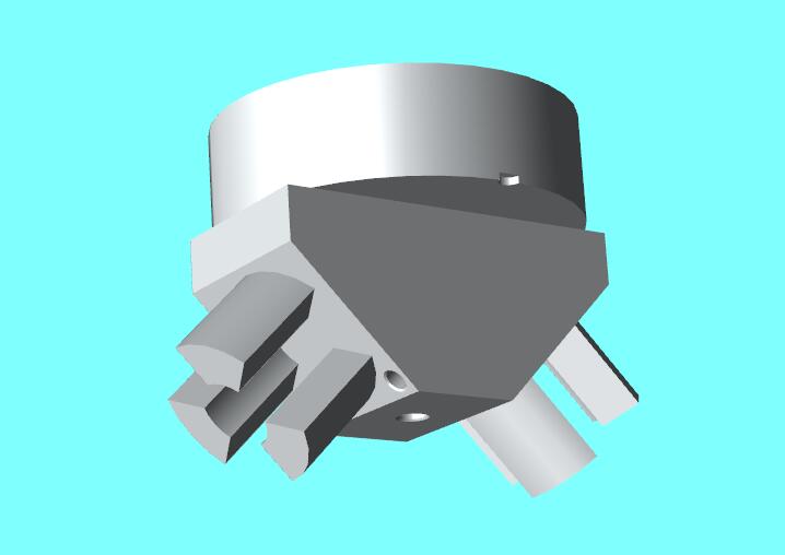
The TCP offsets can be determined by doing a tool calibration
(see MLxRobotCalcToolCalib
– Calculate tool offset and orientation from 5 taught positions.).
Usually a special calibration tip is mounted to teach the calibration positions very precisely. However, the resulting tool offsets are then for the calibration tip and not for the desired gripper. Luckily we can use some matrix calculations to calculate the tool offsets for the gripper. For this we need:
- The tool offsets from the calibration
- The offset information (e.g. from CAD) from the desired gripper to the calibration tip
We will calculate the gripper TCP for two scenarios:
Scenario 1 (easy):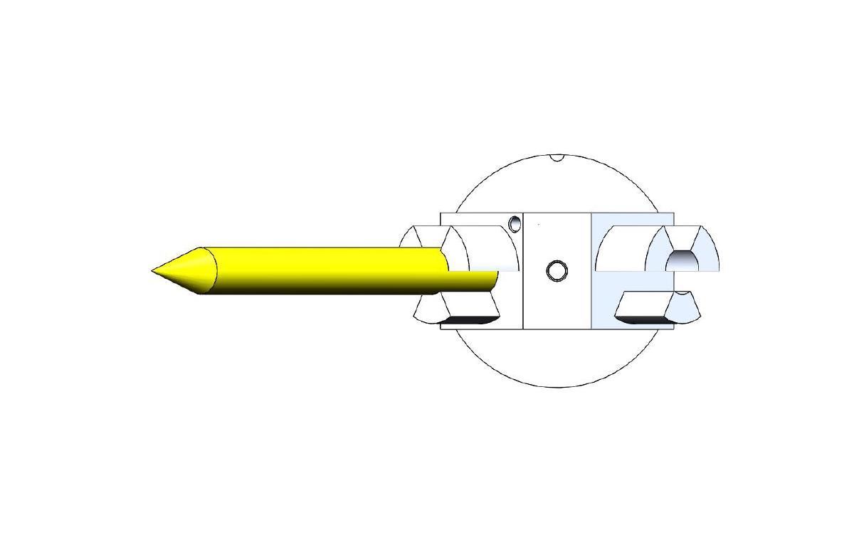
Scenario 2 (more complex):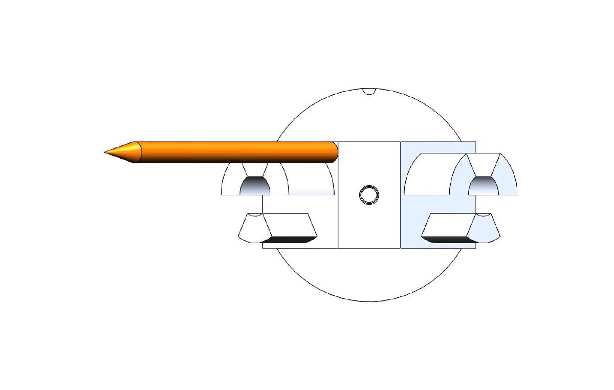
Functions used for this calculation:
MLxxCartesianToMatrix– Convert a cartesian position into a 4x4 transformation matrix.MLxxMatrixToCartesian– Convert a 4x4 transformation matrix into a cartesian position.MLxxMatrixMultiply– Multiply two 4x4 transformation matrices.MLxxMatrixInverse– Calculate the inverse of a 4x4 transformation matrix.
TCPs
The following four TCPs are defined:
1) Flange: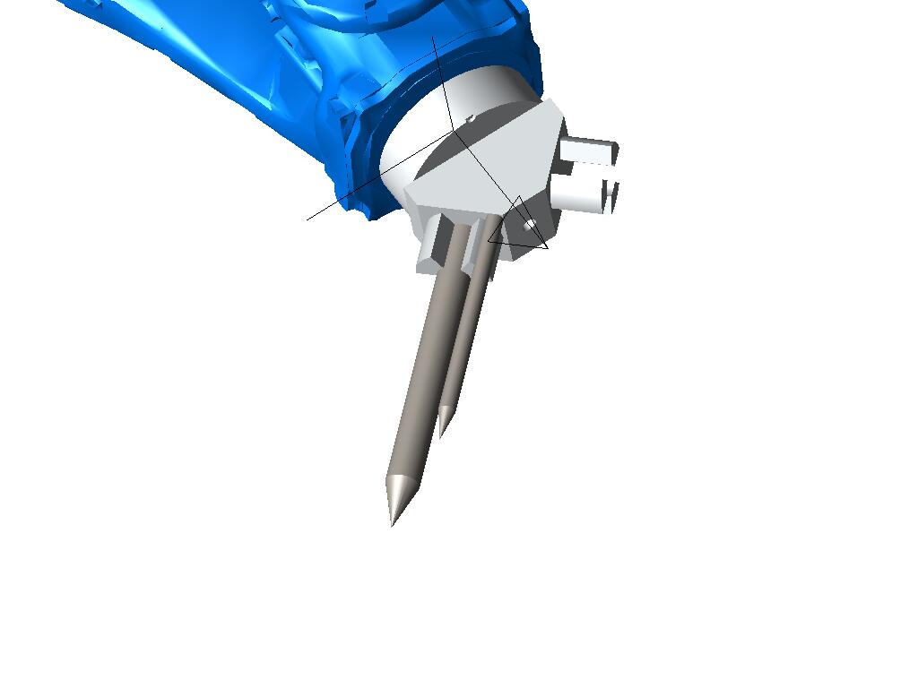
2) Gripper 1: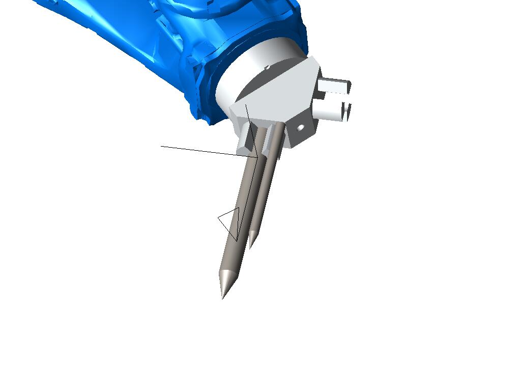
3) Calibration tip (scenario 1):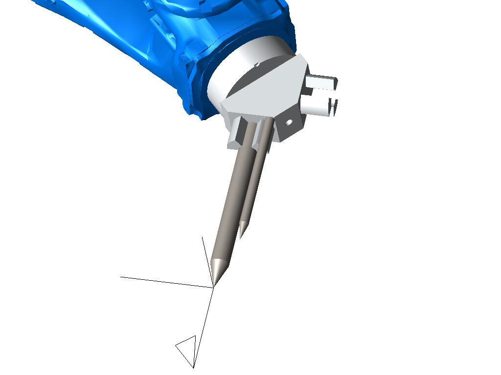
4) Calibration tip (scenario 2):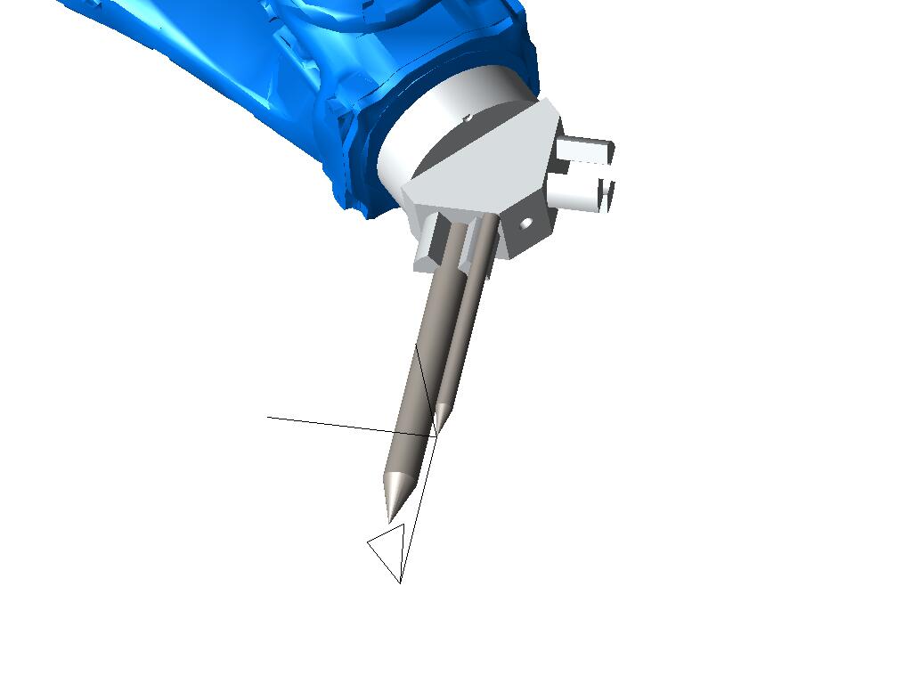
Work flow
stateDiagram-v2

state "TCP calibration tip" as T3
T3 : get data from calibration

state "Calibration tip offset" as O1
O1 : get offset gripper to tip from CAD

state "result" as T1
T1 : TCP data of the gripper

state "MLxxCartesianToMatrix()" as CM1
CM1: convert to matrix

state "MLxxCartesianToMatrix()" as CM2
CM2: convert to matrix

state "MLxxMatrixInverse()" as MI1
MI1: invert the matrix

state "MLxxMatrixMultiply()" as MM1
MM1: multiply the matrices

state "MLxxMatrixToCartesian()" as MC1
MC1: convert to cartesian

O1 --> CM2 : aTipOffset
CM2 --> MI1 : stTipOffsetMatrix
MI1 --> MM1 : stTipOffsetMatrixInv

T3 --> CM1 : aTipTcp
CM1 --> MM1 : stTipTcpMatrix

MM1 --> MC1 : stGripperTcpMatrix
MC1 --> T1 : aGripperTcp
Source code
Declarations
VAR
  nScenario : SINT; (*scenario selection (1=calibration tip mounted in gripper, 2=calibration tip mounted elsewhere)*)
  aTipTcp : ARRAY[0..5] OF REAL; (*TCP calibration tip (from tool calibration) [X/Y/Z/Rx/Ry/Rz]*)
  aTipOffset : ARRAY[0..5] OF REAL; (*offset from gripper to calibration tip (from CAD) [X/Y/Z/Rx/Ry/Rz]*)
  aGripperTcp : ARRAY[0..5] OF REAL; (*TCP for the desired gripper [X/Y/Z/Rx/Ry/Rz]*)
  stTipTcpMatrix : MLxMatrix;
  stTipOffsetMatrix : MLxMatrix;
  stTipOffsetMatrixInv : MLxMatrix;
  stGripperTcpMatrix : MLxMatrix;
END_VAR
Logic
// -----------------------------------------------------------------------------
// Calculate the Tool data for a gripper after it was calibrated
// using a calibration tip
// -----------------------------------------------------------------------------

// -------------------------------------
// Settings
// - aTipTcp: TCP calibration tip (from tool calibration)
// - aTipOffset : offset from gripper to calibration tip (from CAD)
// -------------------------------------

CASE nScenario OF
1:
  // scenario 1: calibration tip mounted in gripper
  aTipTcp[0] := 0; // X
  aTipTcp[1] := 173.74; // Y
  aTipTcp[2] := 203.74; // Z
  aTipTcp[3] := -45; // Rx
  aTipTcp[4] := 0; // Ry
  aTipTcp[5] := 0; // Rz

  aTipOffset[0] := 0;
  aTipOffset[1] := 0;
  aTipOffset[2] := 170;
  aTipOffset[3] := 0;
  aTipOffset[4] := 0;
  aTipOffset[5] := 0;

ELSE
  // scenario 2: calibration tip mounted elsewhere
  aTipTcp[0] := 20;
  aTipTcp[1] := 124.25;
  aTipTcp[2] := 182.53;
  aTipTcp[3] := -45;
  aTipTcp[4] := 0;
  aTipTcp[5] := 0;

  aTipOffset[0] := 20;
  aTipOffset[1] := -20;
  aTipOffset[2] := 120;
  aTipOffset[3] := 0;
  aTipOffset[4] := 0;
  aTipOffset[5] := 0;
END_CASE;


// -------------------------------------
// transformation matrix: calibration tip
// -------------------------------------
MLxxCartesianToMatrix(
  TCPPosition := aTipTcp,
  Result := stTipTcpMatrix);


// -------------------------------------
// transformation matrix: vector from gripper to calibration tip
// -------------------------------------
MLxxCartesianToMatrix(
  TCPPosition := aTipOffset,
  Result := stTipOffsetMatrix);

MLxxMatrixInverse(
  Matrix := stTipOffsetMatrix,
  Result := stTipOffsetMatrixInv);


// -------------------------------------
// transformation matrix: gripper
// -------------------------------------
MLxxMatrixMultiply(
  Matrix1 := stTipTcpMatrix,
  Matrix2 := stTipOffsetMatrixInv,
  Result := stGripperTcpMatrix);


// -------------------------------------
// TCP: gripper
// -------------------------------------
MLxxMatrixToCartesian(
  Matrix := stGripperTcpMatrix,
  Result := aGripperTcp);


// aGripperTcp can now be copied to the gripper tool data e.g.
// Tools[1].ToolOffset := aGripperTcp;
