
Tools command are used to select a tool before performing any robot motion. Any subsequent motion will use the selected tool.
Setting a tool is essential as it contains 2 important data used for handling robot trajectories:
- The Tool Center Point (TCP) offset and orientation
- The Mass properties data including the mass, center of mass and moments of inertia
If no Mass properties are defined, robot will move slowly.
Selecting a tool is mandatory before issuing any move command. Otherwise tool #63 will be selected as default.
If FSU option is enabled following restrictions are applied.
MLxRobotSetToolProperties | MLxRobotSelectTool | |
|---|---|---|
| FSU disabled | yes | yes |
| FSU enabled | not supported | yes |
Library components
| Data types | |
|---|---|
MLxAppDataTool | Data type for storing tool data. |
MLxAxisPosition | Data type for storing an axis position. |
| Function blocks | |
|---|---|
MLxRobotCalcToolCalib | Calculate tool offset and orientation from 5 taught positions. |
MLxRobotSelectTool | Select the active tool of the robot. FSU systems require tool selection by both function block and safety wiring/-fieldbus. |
MLxRobotSetToolProperties | Write tool data to the robot controller and set it as the active tool. Not allowed for FSU systems. |
Availability
Available on all robot and controller.
Parameters
N/A
Write tool data using MLxRobotSetToolProperties
MLxRobotSetToolProperties is used to write tool data to a tool (represented by
ToolNumber between #0 and #63).
The ToolData structure contains the following informations:
- TCP offset position
[X,Y,Z,Rx,Ry,Rz]in mm or degrees - Mass in Kg
- Position of the center of gravity
[Xg,Yg,Zg]in mm - Moments of Inertia
[Ix,Iy,Iz]in Kg.m²
Moreover, this function block select the modified tool to be the current tool.
Using tool with the FSU option enabled
MLxRobotSetToolProperties cannot be used with FSU function enabled.
Instead, tool data must be set using the Teach Pendant (see the corresponding section).
Tool selection is handled by function block MLxRobotSelectTool.
This function block does not edit the tool data and can be used with FSU
enabled.
Select an already created tool using MLxRobotSelectTool
MLxRobotSelectTool is used to select an existing tool as the current tool.
It takes the index of the desired tool as an input.
ToolData parameter can be edited for HMI purpose but it is not mandatory.
It does not effect the tool data stored in the robot controller.
Write a tool data using the teach pendant
If FSU function is activated, tool data should be edited using the Teach Pendant.
- Log in Safety mode
- Go to ROBOT » TOOL
- Put the cursor on the desired tool number and press SELECT
- Modify tool values
- Press READBACK » WRITE » YES to confirm tool data
Tool numbering used in Teach Pendant correspond to MotoLogix.
There is no shift. Tool 0 in MotoLogix refers to Tool #0 in the Teach Pendant.
Effects of tool data
Tool Center Point is significant when a robot position is saved as a cartesian position (usually referred as TCP position). When performing a motion to a cartesian position, the TCP goes to this position until they coincide.
This means that performing a motion to a cartesian position with two different TCP results in a different robot axis position.
Tool Center Point also effects linear-interpolation motion. The TCP moves along a line to the final position. Rotations during a linear-interpolation motion are applied around the TCP.

Mass properties have an effect on the robot axis acceleration and deceleration. It is easier to apply change of speed on a light tool than on a heavier tool. So for the same trajectory, the cycle time with a light tool will be smaller than the cycle time with a heavy tool.
It is important that the Mass properties of the tool correspond to the real load. If the stated mass of a tool is less than the real mass, greater acceleration and deceleration will be applied on robot axis, making the gear reducer wear faster. On the contrary, overrate the mass is not a problem. But the cycle time will increase as the robot decreases its acceleration and deceleration.
In the case of a gripper, the Mass properties should be the combination of the gripper and its load. If the gripper must handle different types of load, select the least favorable load.
At least Mass and CenterOfGravity parameters must be set to non-zero values
so the robot do not move slowly at safety speed.
Case of Tool 0
Tool 0 TCP is often kept on the robot flange (all ToolOffset values at 0).
Doing so makes it easier to perform a motion with no particular tool, like
falling back to home position.
However, Mass properties of tool 0 shall be set to non-zero value.
Otherwise robot will move slowly at safety speed.
Trajectory using several tools
Many applications require several tools, either a dual-gripper tool or a tool changer system is mounted on the robot flange. In that case, several TCP are needed.

In some trajectory, a movement using one tool follow a movement using another tool. In that case the following can be performed :
- Move to Point 1 with Tool 1
- Write Tool 2 data using
MLxRobotSetToolProperties - Move to Point 2 with Tool 2
However MLxRobotSetToolProperties needs the robot to be at standstill, meaning
that the robot has to stop during the trajectory.
This scenario can be avoided by writing every tool data once at system startup
in different tool number using MLxRobotSetToolProperties.
Then the tool change would be performed by the MLxRobotSelectTool function
block.
- Move to Point 1 with Tool 1
- Select Tool 2 using
MLxRobotSelectTool - Move to Point 2 with Tool 2
Example
Example below uses MLxRobotSetToolProperties command to write Tool #0.
MLxRobotSelectTool works the same way except that the ToolData parameter
do not need to be initialize to non-zero value.
Tools : Array[0..0] OF MLxAppDataTool;
FB_MLxRobotSetToolProperties : ARRAY[0..0] OF MLxRobotSetToolProperties;

Tools[0].ToolOffset[0]                             := 150;     // X
Tools[0].ToolOffset[1]                             := 0;       // Y
Tools[0].ToolOffset[2]                             := 200;     // Z

Tools[0].ToolOffset[3]                             := 0;       // Rx
Tools[0].ToolOffset[4]                             := 0;       // Ry
Tools[0].ToolOffset[5]                             := 0;       // Rz

Tools[0].Mass                                      := 5.0;     // Mass

Tools[0].CenterOfGravity[0]                        := 50;      // Xg
Tools[0].CenterOfGravity[1]                        := 0;       // Yg
Tools[0].CenterOfGravity[2]                        := 150;     // Zg

Tools[0].MomentOfInertia[0]                        := 0.1;     // Ix
Tools[0].MomentOfInertia[1]                        := 0.01;    // Iy
Tools[0].MomentOfInertia[2]                        := 0.3;     // Iz

FB_MLxRobotSetToolProperties[0].RobotNumber := 0;
FB_MLxRobotSetToolProperties[0].ToolData := Tools[0];
FB_MLxRobotSetToolProperties[0].ToolNumber := 0;
FB_MLxRobotSetToolProperties[0]( MLX := dummy, );
Tool calibration
If the ToolOffset data for the used tool is not available or the tool was
bend due to a collision, you can use MLxRobotCalcToolCalib to
let the robot controller calculate the tool offsets for you.
This process is called tool calibration.
There are three ways to calibrate the tool:
- Offset: calibrate TCP offset position (
X/Y/Z) from 5 taught positions. - Posture: calibrate TCP orientation (
Rx/Ry/Rz) from a single taught position. - Offset + Posture: calibrate both TCP offset position and -orientation
(
X/Y/Z/Rx/Ry/Rz) from 5 taught positions.
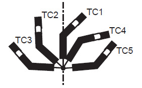
Offset
To calibrate X/Y/Z of the tool, five different orientations (TC1-TC5)
must be taught with the TCP as the reference position.
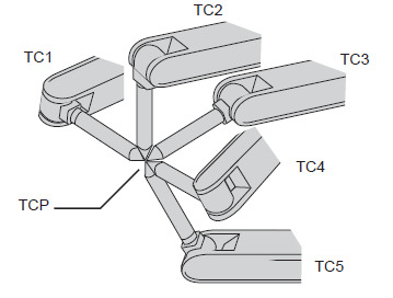
- Each orientation must be arbitrary.
- Accuracy may decrease when pose setting is rotated in a constant direction.
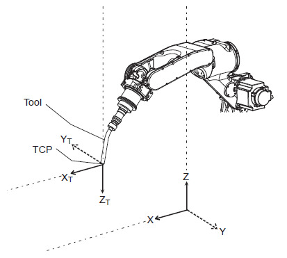
Posture
To calibrate Rx/Ry/Rz of the tool, a single position (TC1) must be taught
with the Z-axis of the desired tool coordinates pointing
vertically downward to the ground.
Offset + Posture
To calibrate X/Y/Z/Rx/Ry/Rz of the tool, first teach TC1 with the
Z-axis of the desired tool coordinates pointing vertically downward
to the ground.
Then teach the other teaching points (TC2-TC5) with all tool points
meeting at the TC1’s tool point as shown in the figure below.
Coord calibration and
then do the Posture calibration in another position.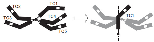
Example
Below pseudo code gives you an idea of the program structure for using Tool calibration.
// teach `TC1`
10  <jog the robot>
// store actual axis position
11  MLxxCopyAxisDataToReal(
      AxisData := GlobalVar.MLX[0].Robot[0].RobotAxes,
      RealOut  := myRobotPosition[0]);

// teach `TC2`
20  <jog the robot>
21  MLxxCopyAxisDataToReal(
      AxisData := GlobalVar.MLX[0].Robot[0].RobotAxes,
      RealOut  := myRobotPosition[1]);

// teach `TC3`
30  <jog the robot>
31  MLxxCopyAxisDataToReal(...)

// teach `TC4`
40  <jog the robot>
41  MLxxCopyAxisDataToReal(...)

// teach `TC5`
50  <jog the robot>
51  MLxxCopyAxisDataToReal(...)

// execute the calibration command
60  MLxRobotCalcToolCalib(...)

// store the calculated tool data
70  myToolsArray[0].ToolOffset := MLxRobotCalcToolCalib.ToolOffset;