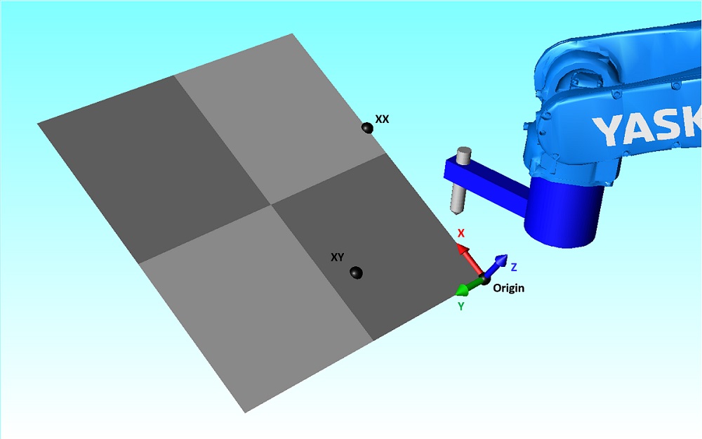
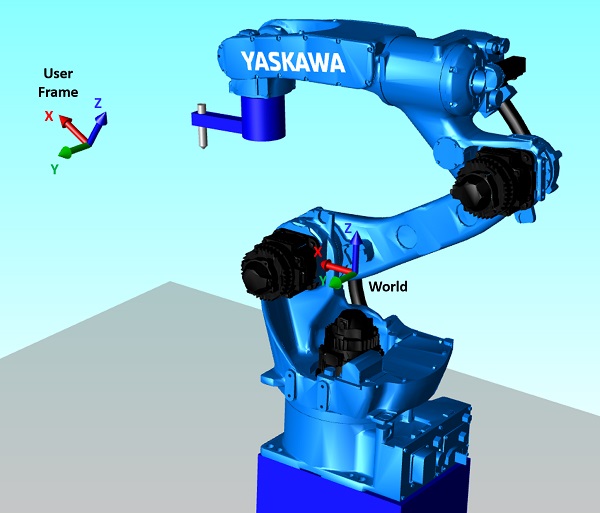
A User Frame is a user defined coordinate system. User Frames make programming trajectories far more intuitive as the positions relate to the object of your choice.
User Frames can be created by 2 methods:
- 3 points teaching
- coordinates
Both methods use the same function block MLxRobotSetUserFrame.
A User Frames can be set on the fly during a trajectory. It is then added to the queue and apply to all subsequent motions.
Library components
| Data types | |
|---|---|
MLxAppDataUserFrame | Data type for storing user frame data. |
| Function blocks | |
|---|---|
MLxRobotSetFrameShift | Shift all following motion commands by an offset. |
MLxRobotSetUserFrame | Write user frame data to the robot controller (volatile memory) and set it as the active user frame. |
Availability
Available on all robot and controller.
Parameters
N/A
Create a User Frame with 3 points teaching
Principle
This method is used when the User Frame must be related to a mechanical element or a workstation. It can be a pallet, a conveyor, …
It is especially useful for tilted planes or workstation misaligned with the WORLD frame.
However this method need a calibration tip mounted on the tool of the robot and the corresponding TCP must be taught. So this method takes more time to implement but provides an accurate UserFrame.
Implementation
3 points are required. Their coordinates must be written in the
MLxAppDataUserFrame data structure.
Originis the origin of the User FrameXXgives the X directionXYgives the XY plane orientation

MLxAppDataUserFrame.UserFrameType must be set to 1 to use 3 points teaching.The MLxAppDataUserFrame data structure is then passed as an input to the
MLxRobotSetUserFrame function block to create the User Frame.
Example
UserFrames : ARRAY[0..0] OF MLxAppDataUserFrame;
FB_MLxRobotSetUserFrame : ARRAY[0..0] OF MLxRobotSetUserFrame;

UserFrames[0].UserFrameType := 1;      // Use 3 points teaching

UserFrames[0].Origin[0] := 400;        // ORG X
UserFrames[0].Origin[1] := 100;        // ORG Y
UserFrames[0].Origin[2] := 300;        // ORG Z

UserFrames[0].XX[0] := 600;            // XX X
UserFrames[0].XX[1] := 100;            // XX Y
UserFrames[0].XX[2] := 450;            // XX Z

UserFrames[0].XY[0] := 450;            // XY X
UserFrames[0].XY[1] := 300;            // XY Y
UserFrames[0].XY[2] := 350;            // XY Z

FB_MLxRobotSetUserFrame.RobotNumber                 := 0;
FB_MLxRobotSetUserFrame.UserFrameNumber             := 0;
FB_MLxRobotSetUserFrame.UserFrameData               := UserFrames[0];
FB_MLxRobotSetUserFrame[0]( MLX := dummy, );
Create a User Frame with coordinates
Principle
This method is used when a User Frame is calculated.
This method is fast to implement as it does not need any hardware and only requires internal calculations. It is useful for calculating a pick and place trajectory and for shifting an already set User Frame. Moreover, calculation and setting of a User Frame can be done on the fly during a trajectory.
However the result may be misaligned with the workstation as no calibration with the mechanical environment is needed.
Implementation
Origin coordinates and orientation [X,Y,Z,Rx,Ry,Rz] are expressed in the
WORLD frame.
They must be passed to the MLxAppDataUserFrame.CoordFrame[] data structure.
MLxAppDataUserFrame.UserFrameType must be set to 0 to use this method.
The MLxAppDataUserFrame data structure is then passed as an input to the
MLxRobotSetUserFrame function block to create the User Frame.
Example
UserFrames : ARRAY[0..0] OF MLxAppDataUserFrame;
FB_MLxRobotSetUserFrame : ARRAY[0..0] OF MLxRobotSetUserFrame;

UserFrames[0].UserFrameType                        := 0;

UserFrames[0].CoordFrame[0]                        := 350;     // X
UserFrames[0].CoordFrame[1]                        := 100;     // Y
UserFrames[0].CoordFrame[2]                        := 400;     // Z
UserFrames[0].CoordFrame[3]                        := 0;       // Rx
UserFrames[0].CoordFrame[4]                        := -30;     // Ry
UserFrames[0].CoordFrame[5]                        := 0;       // Rz

FB_MLxRobotSetUserFrame.RobotNumber                 := 0;
FB_MLxRobotSetUserFrame.UserFrameNumber             := 1;
FB_MLxRobotSetUserFrame.UserFrameData               := UserFrames[0];
FB_MLxRobotSetUserFrame[0]( MLX := dummy, );
Using User Frames with the Teach Pendant
Unlike tools, User Frames are not written in the Yaskawa controller. Hence, it is not visible on the teach pendant in menu ROBOT » USER COORDINATE. Neither it is possible to jog in these User Frames using the Teach Pendant.
However it is possible to write User Frames previously set by
MLxRobotSetUserFrame in the Yaskawa controller using
MLxWriteApplicationDataToYRC.
In that case, User Frames 0 will be written in UF#1 of the Teach Pendant.
User Frames of the teach pendant range from UF#1 to UF#64, meaning that
MotoLogix UserFrameNumber parameter must not exceed 63.