Software version
YAS4.26 (or newer).Setup steps
Install fieldbus board
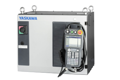
Mount the option board in the robot controller.Setup MotoLogix
Activate the (paid) option function (by Yaskawa) and setup MotoLogix for the desired fieldbus and PLC architecture.Setup fieldbus
Define the fieldbus data packet for MotoLogix.Set parameters
Set the internal parameters required for MotoLogix usage.
The setup process requires the robot controller to be in maintenance mode
and a sufficient authorization level (management or higher).
Read more...
Activate maintenance mode:
- Power off
- Press (and hold) main menu
- Power on
- Release main menu when the beeping sound is heard (usually within a few seconds)
Change the authorization level:
- system » security » select
- select the desired level using ▼ ▲ » select
- enter the password and press enter
Install fieldbus board
Yaskawa robot controllers use various fieldbus solutions:
| type | description |
|---|---|
PCI | Large form factor option board |
PCIe | Compact form factor option board |
cpu board | Software option (uses the built-in LAN port) |
Mounting the AB3617 board
PCI board.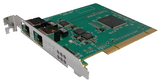
Read more...
This board can be mounted in the following installation frames (riser boards):
| type | description |
|---|---|
JANCD-ABB03-E | 2xPCI |
JANCD-ABB04-E | 1xPCI, 1xPCIe |
Loosen the screws and remove the installation frame from the CPU rack:
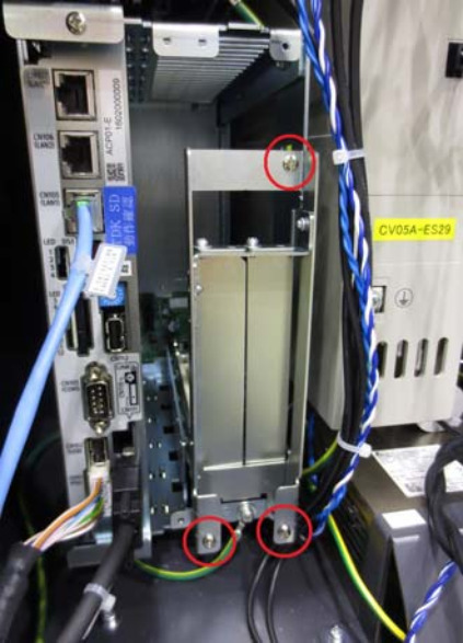
Installation frame Insert the PCI card into the corresponding slot (1 or 2) and tighten the screw:
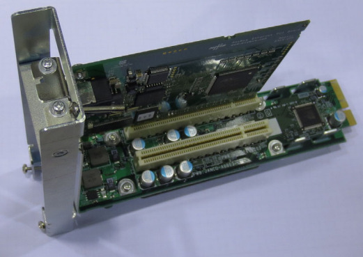
Insert PCI card into the slot Install the installation frame into the CPU rack and fasten it again with the screws:
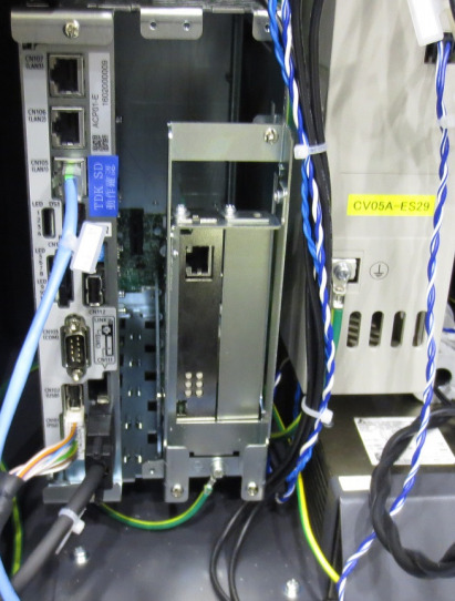
Installed installation frame
Mounting the INPACT board
PCIe board.
Read more...
This board can be mounted in the following installation frames (riser boards):
| type | description |
|---|---|
JANCD-ABB02-E | 2xPCIe |
JANCD-ABB04-E | 1xPCI, 1xPCIe |
Loosen the screws and remove the installation frame from the CPU rack:

Installation frame Insert the PCIe card into the corresponding slot (1 or 2) and tighten the screw:

Insert PCIe card into the slot Install the installation frame into the CPU rack and fasten it again with the screws:

Installed installation frame
Setup MotoLogix
Open the MotoLogix option function settings: system » setup » option function » motologix

MotoLogix option function Customers: Please contact Yaskawa if the MotoLogix option function is not available in the list.Activate the MotoLogix option function:
This requiresYaskawaauthorization level and cannot be changed by the customer.
MotoLogix settings Enter the settings:
item value FUNCTION ENABLEDCONNECTION TYPE ETHERCATENDIANNESS LITTLECustomers can disable MotoLogix afterwards by settingFUNCTIONtoDISABLED.TheENDIANNESS(byte order) depends on the PLC cpu architecture.Use enter to confirm and leave the settings screen.
Setup fieldbus
AB3617 board settings
Read more...
Open the board settings: system » setup » option board » AB3617

Option boards Enter the settings:

EtherCAT settings item value AB3617 USED (MotoLogix)IO SIZE + MotoLogix 0 dword + 109 dwordCustomers can adjust these default settings to their needs.
Example: To add an optional non-MotoLogix data packet of e.g.
32 byteset the value to8 dword + 109 dword.The size of theMotoLogixdata packet is fixed and shall not be changed.Adding a non-MotoLogix data packet might require to change/shift the address mapping of the MotoLogix data packet in the PLC.Use enter (multiple times) to confirm this- and the following screens. Don’t make any changes in these following screens (keep default IO allocation).
INPACT board settings
Read more...
ECTOpen the board settings: system » setup » option board » inpact

Option boards Enter the settings:
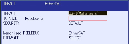
EtherCAT settings item value INPACT USED (MotoLogix)IO SIZE + MotoLogix 0 dword + 109 dwordCustomers can adjust these default settings to their needs.
Example: To add an optional non-MotoLogix data packet of e.g.
32 byteset the value to8 dword + 109 dword.The size of theMotoLogixdata packet is fixed and shall not be changed.Adding a non-MotoLogix data packet might require to change/shift the address mapping of the MotoLogix data packet in the PLC.Use enter (multiple times) to confirm this- and the following screens. Don’t make any changes in these following screens (keep default IO allocation).
Parameter settings
Read more...
| parameter | value |
|---|---|
| FD 6 | 7 |
| FD 7 | 1 |
| FD 164 | 1 |
| FD 256 | 2 |
| MF1G 4 | 55 |
| RS 475 | 3 |
| S1C1G 57 | 0 |
| S1D 199 | 1 |
| S1D 229 | 0 |
| S1D 233 | 0 |
| S1D 256 | 2 |
| S2C 221 | 0 |
| S2C 244 | 2 |
| S2C 316 | 1 |
| S2C 541 | 0 |
| S2C 542 | 0 |
| S2C 869 | 1 |
| S2C 1015 | 2 |
| S2C 1139 | 0 |
| S2C 1142 | 6 |
| S2C 1147 | 0 |
| S2C 1205 | 1 |
| S2C 1419 | 1 |
| S2C 1586 | 1 |
| S2C 1702 | 1 |
| S2C 1703 | 1 |
| S2C 1704 | 1 |
| S3C 1380 | 50 |
| S3C 1385 | 100 |
| S3C 1387 | 1 |
